
Pulse valve model specification representation and basis
2025-02-25
1. Pulse valve specifications are expressed in terms of the inner diameter of the connecting pipe configured at its output port.
The identification of a pulse valve consists of two parts: the model number and the specification. The model number is indicated by the letter chosen by each manufacturer, reflecting the control mode and classification of the pulse valve (right-angle valve, submerged valve, etc.). Pulse valve specifications are expressed, whether by industry standards or domestic and foreign production plants are accustomed to pulse valve output port configuration of the connecting pipe inner diameter, expressed in inches or millimetres. With the progress of bag filter technology and market demand, dust collector to large and long bag direction, the need for a large blowing volume, the shape and size of the bag suitable for the arrangement of row spacing large diameter valve and its supporting. A few years ago on the market with the size of the external dimensions of the 3 ‘(76mm) submerged valve the same size, diaphragm diameter of the same 200mm 4 '(102mm) pulse valve. And in many occasions are used, but its blowing effect caused doubts. We can see from Figure 1 that the valve said 4 ‘or 102mm is the inner diameter of the output port rather than its configuration of the inner diameter of the connecting pipe, so both from the basis of the pulse valve specifications, or from the actual blowing effect it is not a real 4' (102mm) pulse valve, from the output port configuration of the connecting pipe diameter, at most, is a 3.5' (89mm) pulse valve.

Figure 1, Nominal 4' (102mm) Pulse Valve Dimensions
2. Only expanding the output diameter of the pulse valve does not increase the blowing air volume accordingly.
Obviously the size of the pulse valve blowing volume depends not only on the output calibre, but also depends on the airflow flow channel volume and the valve opening (pulse valve opening diaphragm stroke), the flow channel volume and the increase in opening, so that the valve itself to reduce resistance, is to increase the volume of blowing gas and improve the performance of the prerequisites for blowing. From Figure 1 and Figure 2 can be seen that the so-called ‘4' ‘(102mm) valve is the 3' (76mm) valve body output port diameter expanded to 4' (102mm), thus reducing the valve body flow path volume; In addition, in the diameter of 200mm diaphragm to expand the diameter of the output sealing piece (so that it can seal the outer diameter of 102mm output), so that it can seal the outer diameter of 102mm. 102mm output), thereby reducing the diaphragm range of motion and reducing the valve opening. A 4‘ (102mm) I.D. output port with a 3.5' (89mm) I.D. connecting tube has a smaller gas flow path volume and diaphragm range of motion than a 3' valve, resulting in an increase in the resistance of the pulse valve itself. Although the inner diameter of 3.5 ‘(89mm) than 3' (76mm) of the connecting pipe cross-sectional area increased by 36%, but because of the rise in the resistance of the valve body, the source of the gas flow into the valve body is subject to constraints on the blowing volume of gas can not be increased accordingly. Currently on the market will be this kind of pulse valve called ‘small 4' valve ‘or' false 4 ‘valve', that the user has noticed that this is not a normal 4' pulse valve.
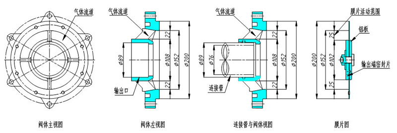
Figure 2, 3’ (76mm) Pulse Valve Structure Dimensions
3. Expanding the output calibre of the pulse valve and reducing its size cannot be achieved at the same time.
Pulse valve rely on the diaphragm before and after the two air chamber pressure changes in the diaphragm around the deformation to achieve the opening and closing of the pulse valve (see Figure 3), in order to get a larger volume of blowing air not only need to expand the pulse valve output configuration connecting the inner diameter of the pipe, and at the same time the need to increase the valve's flow channel volume and openness (stroke), which requires the configuration of a larger diameter of the diaphragm. Generally speaking, the pulse valve output configuration of the inner diameter of the connecting pipe increased by 1’ (25mm), the diaphragm diameter needs to be increased by 30mm, and the diaphragm diameter to determine the volume of the pulse valve, it can be seen that the expansion of the pulse valve output calibre and reduce the size of the valve can not be achieved at the same time.
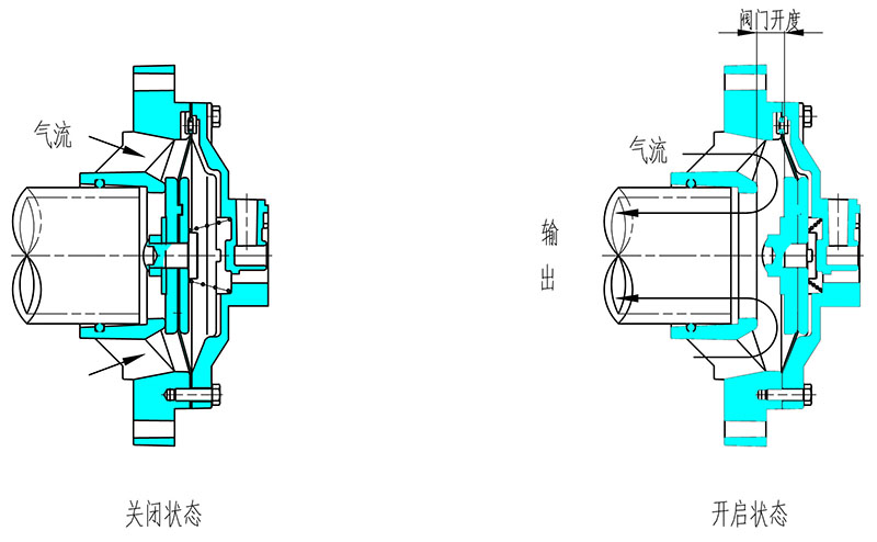
Figure 3, working diagram of the pulse valve


X
We use cookies to offer you a better browsing experience, analyze site traffic and personalize content. By using this site, you agree to our use of cookies.
Privacy Policy